The dock is where a warehouse makes its money. Throughput, trailer exchange speed, damage rates at loading — all of it traces back to the dock door, dock leveler, and the pit that carries the leveler. Building the pit wrong means retrofitting it later, which means breaking out concrete in an occupied warehouse and losing operational days.
Florida adds a few specific complications to dock pit construction: the water table, the concrete durability requirements in coastal environments, and the drainage standards that prevent standing water in a pit that sits below finished floor.
Here's how dock leveler pits are built correctly in Florida industrial construction.
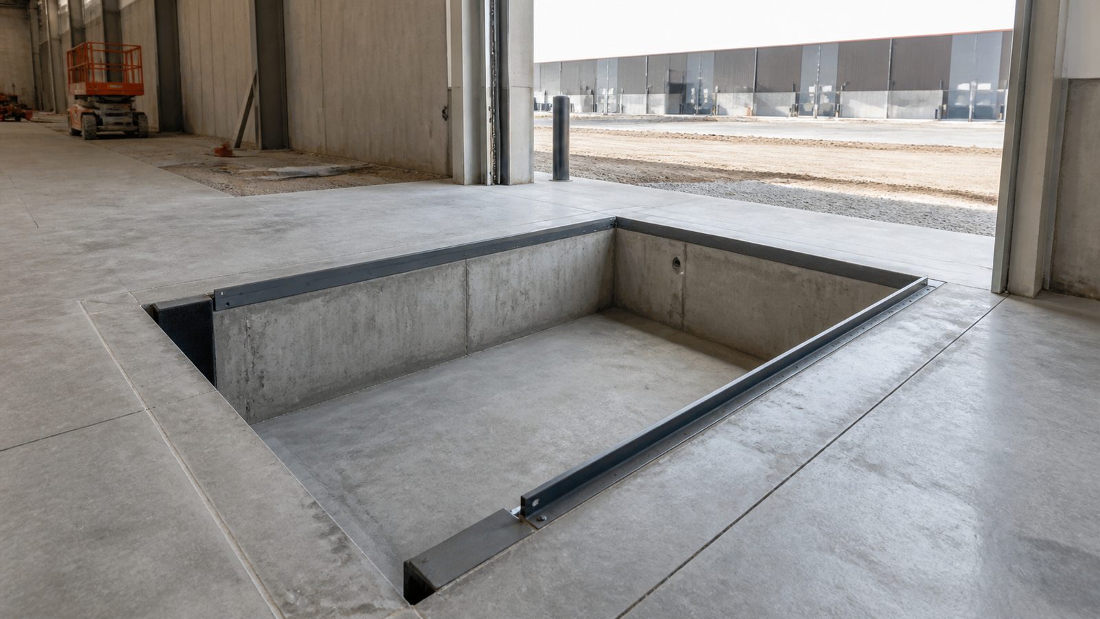
Dock Leveler Types and What Each Requires From the Pit
The pit design depends entirely on the leveler type. The three most common in Florida warehouse construction:
Mechanical Dock Levelers
Mechanical levelers are spring-activated. The operator releases a pull chain, the platform rises, and they walk it down to the trailer bed. These are the most economical option and the most common in standard distribution applications.
Pit dimensions for a standard mechanical leveler: 6 feet 6 inches wide x 8 feet deep x the pit width matching the door opening (typically 8 or 9 feet). The pit must be dimensioned to the leveler manufacturer's exact spec — Rite-Hite, Serco, Kelley, and Blue Giant all have specific requirements, and using the wrong pit dimension is the most common installation problem we encounter on projects where the GC and equipment supplier aren't coordinating upfront.
Hydraulic Dock Levelers
Hydraulic levelers use a power unit to raise and position the platform. They're smoother in operation, support higher capacity ratings, and last longer in high-cycle applications. The pit is dimensioned the same as a mechanical leveler for the leveler itself, but requires a power unit alcove: a 12-inch deep x 12-inch wide recessed area on one side of the pit for the hydraulic pump and reservoir.
The power unit requires a dedicated 20-amp circuit at 115V or 230V depending on the unit. That circuit needs to be stubbed into the pit during rough electrical — it's a common miss when the electrical sub doesn't receive the equipment spec before rough-in.
Vertical Storing Dock Levelers (VSDL)
VSDLs have no pit. The platform stores vertically inside the building against the dock door when not in use. This is the right choice for cold storage facilities where the pit would create a thermal break and condensation problem, and for facilities with high-pressure cleaning requirements where a pit would collect water and debris.
The tradeoff: VSDLs cost $8,000–$15,000 more than a hydraulic leveler per door and require a higher dock door (typically 10 feet instead of the standard 8 or 9 feet) to accommodate the stored platform.
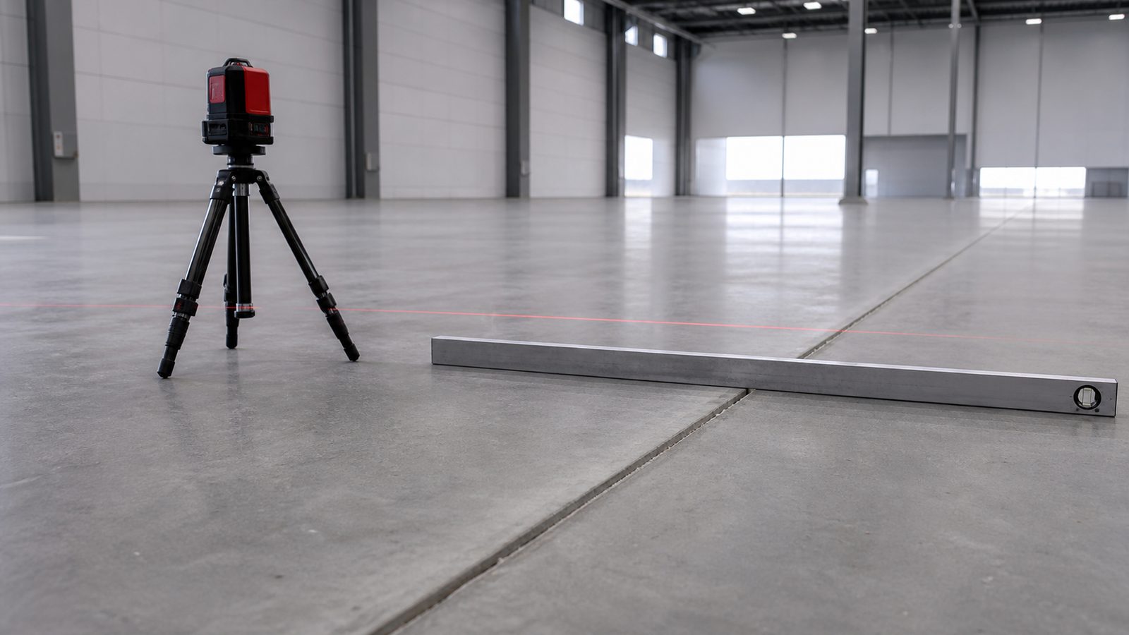
Concrete Specification for Dock Pits in Florida
Standard warehouse slab in Florida is 6-inch concrete at 3,500 psi with wire mesh or rebar. Dock pit walls and floor are a different standard.
Pit Wall Thickness and Reinforcement
Dock pit walls must resist the point load of a trailer backing into the dock bumpers at speed, and the outward pressure of the forklift wheel load at the pit lip. Standard dock pit wall spec:
- 12-inch concrete walls (not 8-inch — the dock bumper anchor bolts need embedment depth that 8-inch walls can't provide reliably)
- #5 rebar at 12 inches on center, each way, in the wall
- #5 continuous rebar at the pit lip (the top of the wall where the leveler frame sits), doubled at corners
The pit lip is the highest-stress point. Forklift forks approach the leveler, the weight shifts, and the pit lip carries concentrated wheel loads from a 15,000-pound counterbalanced forklift. Underreinforced pit lips crack in the first year of heavy use.
Pit Floor and Drain
The pit floor is typically 6-inch concrete at 3,500 psi, with a 2% slope toward a center drain or a rear drain. The drain connects to the floor drainage system and must be able to handle both condensation from refrigerated trailers and wash-down water from periodic dock cleaning.
In Florida, the water table proximity determines the drain design. In warehouse sites near Jacksonville's coastal areas or in areas with high water tables (many industrial parks off U.S. 1 and 9A have water table depths of 3–6 feet), a simple gravity drain to the storm system may not work. You need to confirm the invert depth of the available storm drainage connection before designing the pit drain.
For sites where gravity drainage isn't feasible, a sump pump in the pit is the alternative — a submersible pump with a float switch and discharge line that runs to the storm system above the water table level.
Pit Cover Options During Construction
A dock pit in a slab under construction is a fall hazard. OSHA 1926.502 requires fall protection for any opening deeper than 4 feet. Options:
- Temporary pit covers (3/4-inch plywood cut to pit dimensions, labeled and secured)
- Pit covers left in place until leveler installation
- Roped-off exclusion zones around open pits during concrete work in adjacent areas
JK Prestige's OSHA 30-certified superintendents document pit cover placement at every daily site inspection. This is not paperwork theater — a forklift hole in a warehouse slab is a real hazard during the construction phase.
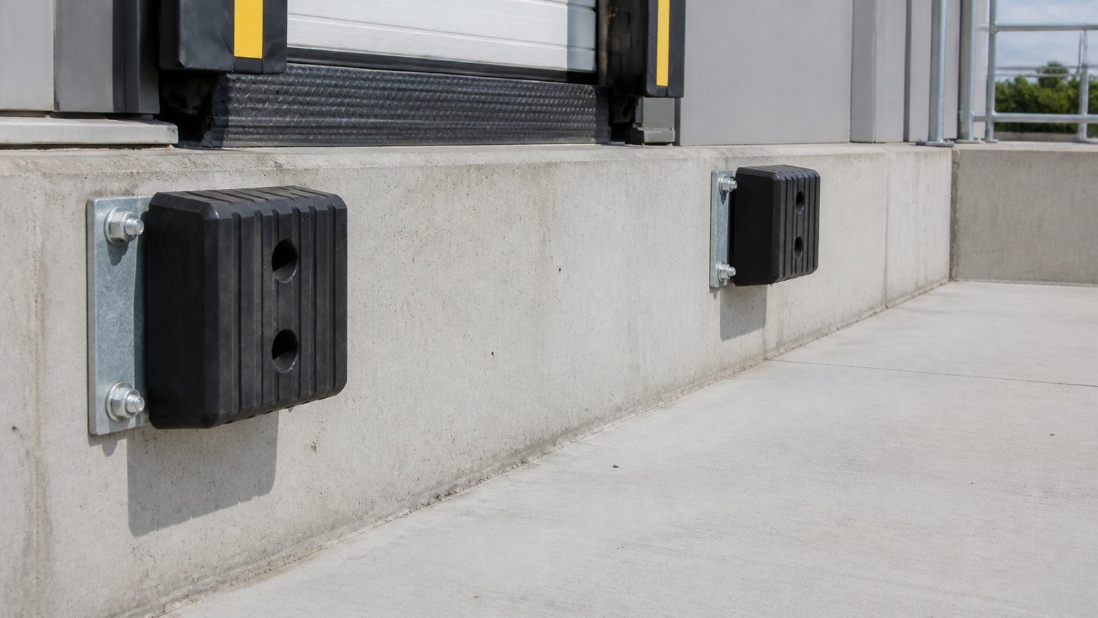
Dock Bumper Anchoring
Dock bumpers absorb the impact of trailers backing to the dock. They're typically laminated rubber or molded urethane, bolted to the dock face with 5/8-inch anchor bolts embedded 6 inches into the concrete.
The dock face — the concrete wall above the pit on the exterior — must be designed for these anchor loads. Standard dock bumper loading is 20,000–40,000 pounds per bumper depending on the maximum trailer weight and typical backing speed. The dock face concrete must be a minimum of 12 inches thick at the bumper location with appropriate reinforcement behind the anchor bolt zone.
This is frequently underdetailed on standard warehouse drawings. The structural engineer may design the pit walls and leave the dock face to "match existing" or to GC standards. If you're building a speculative warehouse in Jacksonville and your structural engineer hasn't specifically designed the dock bumper anchorage, ask them to. The fix is cheap in design; the fix is expensive in construction after the concrete is poured.
Dock Door Frame Placement Relative to the Pit
The dock door frame sets on the exterior wall above the pit. The relationship between the door frame rough opening, the pit centerline, and the dock seal frame determines whether trailers align correctly with the leveler when backed in.
Standard dock door rough opening: 8 feet wide x 8 feet 8 inches tall (for 8 x 9 dock doors, the nominal size used in most Class A and B warehouse construction).
The centerline of the door rough opening must align with the centerline of the pit within 1/4 inch. A misaligned pit — common when the concrete sub and the door frame sub aren't coordinating — causes the leveler to sit off-center in the dock opening and the dock seals to wear unevenly.
JK Prestige coordinates dock pit layout with the door supplier before concrete is poured. We carry the door supplier's rough opening dimensions into the structural drawings and verify alignment at the formwork stage, not the inspection stage.
What Gets Bid Wrong
The dock pit package is frequently split across multiple subs with no coordinator: the concrete sub forms and pours the pit, the electrical sub stubs in power to the pit area without knowing the power unit location, the door supplier installs frames based on architectural drawings that haven't been coordinated with the leveler manufacturer's spec.
When a GC runs the dock package as coordinated scope — with the concrete, electrical, door, and leveler installation coordinated through a single sequence — the dock gets built right the first time.
At JK Prestige, we self-perform concrete on most warehouse projects. That means our team is building the pit, and our superintendent is the coordination point for the door supplier and leveler installer from the day the pit is formed. One phone call. One accountability.
No call center. No coordinator. A JK principal reviews every inquiry and replies with a real number, not a range, not a follow-up form.
Request Free Estimate →